The Importance of Wellbore Integrity for Groundwater Protection in Shale Gas Well Construction.
Authors: Michael Prohaska1,2 and Gerhard Thonhauser1,2
1Faculty of Deep Drilling Technique, University Leoben, Austria
2Environmentally Friendly Drilling Systems (EFD), European Chapter
Published: June 22, 2012
Updated: July 18, 2015
Introduction
One of the major public concerns in shale gas development is the protection of groundwater from fluids that are flowing in a cemented steel casing from the shale gas reservoir to the surface. In the United States, more than 40,000 shale gas wells have been completed in the last two decades.
Following an intensive period of learning, the US shale gas industry slowly moved from prototyping to an economic and industrialized process in order to produce these previously inaccessible resources. This development process is still ongoing. Regulations as well as best practices from the oil and gas industry have had to be adapted to shale gas applications, and where necessary, new regulations defined.
Any onshore wellbore that is drilled for any purpose (oil, gas, water, geothermal, injection, and disposal) needs to have a seal to protect groundwater-bearing strata from drilling fluids, production fluids or work-over fluids. This is a major requirement that must be met - from the very beginning of the entire wellbore construction process and throughout the lifetime of the wellbore, but also for any time after final abandonment. Casing pipe and cement are the barriers that must guarantee groundwater protection.
The cement ensures a solid and continuous connection between wall rock and steel pipe and prevents fluid migration through the space between the casing and wall rock, called the annulus. The number of cemented steel layers to protect groundwater is variable and depends on well depth, rock types and other factors. A schematic sketch of the upper part of a typical well completion is displayed in Figure 1.
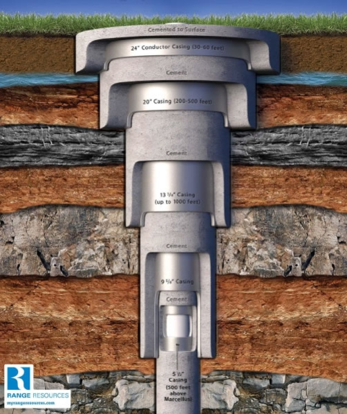 Fig. 1: Sketch of a sequence of cemented casing pipes from a typical wellbore (not to scale).
A wellbore that is drilled for shale gas production purposes has similar integrity requirements to those outlined above. Details on standard well completions and possible scenarios of well integrity failure and resulting leakage are addressed in chapter 3. Chapter 4 focuses on best practice recommendations for shale gas well completions.
It has been discussed that there is a high risk of hydraulically induced fractures penetrating overlaying rock formations, which may create migrations pathways for contaminants. The induced fractures could connect to naturally occurring, permeable faults, or interconnected pore spaces that may allow further fluid migration.
Scientific studies currently discuss the risk of liquids migrating upwards through the rock formations overlaying the fractured reservoir rocks1. While the risk of migration of liquids is probably extremely low, migration of gas, on the other hand, is a more likely scenario. Some studies suggest that natural gas from fractured reservoirs has entered into aquifers, but migration pathways are poorly constrained.2
It should be noted that the process of hydraulic fracturing itself bears little risk of groundwater contamination.3 Most incidents that occur during shale gas production are attributed to procedures and operations peripheral to hydraulic fracturing, such as waste management and disposal as well as production, on-lease transport, and storage, e.g. of chemicals.4
Wellbore integrity and failure scenarios
Casing and cementing are the principal barriers that protect groundwater from fluids which flow in the well drilling and preparation phase or which are produced during the later production phase. To ensure long-term wellbore integrity, it is crucial that the cement composition demonstrates both the required chemistry of the slurry as well as the physical placement of that slurry into the wellbore.
A typical wellbore is constructed from a series of concentric casing strings (Fig. 2). These overlap, especially in the upper sections of the well. Thus, multiple layers of steel and cement usually isolate groundwater-bearing zones. Several options for completion of the upper section of a well in the worst case scenario whereby the production fluid leaks through the production tubing are illustrated in Figure 2. Steel and cement are shown to isolate the outside of the wellbore in the event of well integrity failure caused by a leaking production tubing, with option (A) showing, starting from the outer layers, cement followed by two casing strings.
The top of cement (TOC) of the surface casing is at the ground surface. Note that the TOC of the intermediate casing is some distance below the groundwater bearing rock formation. This is a standard well completion design which is often used for conventional oil and gas wells. Option (B) provides even more groundwater protection with two cement and three casing layers between the inside of the well and the outer, groundwater-rich rocks. Option (C) adds one additional barrier (cement) and thus can be classified as the strongest installation.
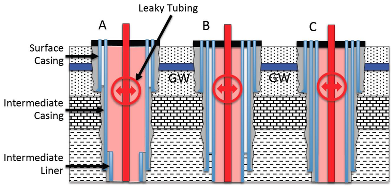 Fig. 2: Principal sketches of casing and cement in the upper part of a gas well. GW=groundwater
Casing and cement do not only act as a barrier to fluids that flow inside the wellbore, they also prevent fluids from flowing into the annulus from outside. The isolation of the inside of the wellbore from the outer environment is generally known as zonal isolation, which is accomplished by a perfectly cemented annulus. Figure 3 shows a perfectly cemented annulus of the horizontal part of a shale gas well, allowing the fluids to flow only in the desired direction, from the induced fractures to the production tubing (Fig. 3).
 Fig. 3: Lower part of a hydraulically fractured natural gas well. The intermediate and production liners are cemented throughout, thus providing perfect zonal isolation between the inside of the well and the surrounding rocks.
Badly cemented sections of a wellbore might occur, especially in highly deviated and horizontal sections. This is caused by bad casing centralization or the failure to rotate long strings, among others. In the case of a badly cemented section, which might allow fluids to migrate along the annulus, the next functional barrier is (a) the liner hanger seal which prevents fluid migration to the inside of the wellbore (Fig. 3) or (b) the cemented casing shoe next to the badly cemented section (Fig 4). Both barriers effectively stop unwanted fluids from continuing to flow.
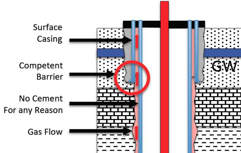 Fig. 4: Competent cement barrier at the casing shoe of the surface casing. If, for any reason, fluids rise along the annulus between the wellbore and the rock formation, the casing shoe of the adjacent casing layer will preclude further flow between rock formation and wellbore. GW=groundwater
The importance of a properly cemented casing shoe is also illustrated in Figure 5. In this figure, the cement of the production section has failed and back-flow or gas can enter the annulus between casing and rock formation. However, the cemented shoe of the prior intermediate casing stops the flow of further fluid. In this case, the only way fluids can continue to flow is across a leaking production liner hanger seal. Liquids and/or gas may then accumulate inside the wellbore, between the production liner and intermediate casing. Contamination of groundwater would not occur in this case as multiple barriers of steel tubes and cement are present in the upper parts of the well.
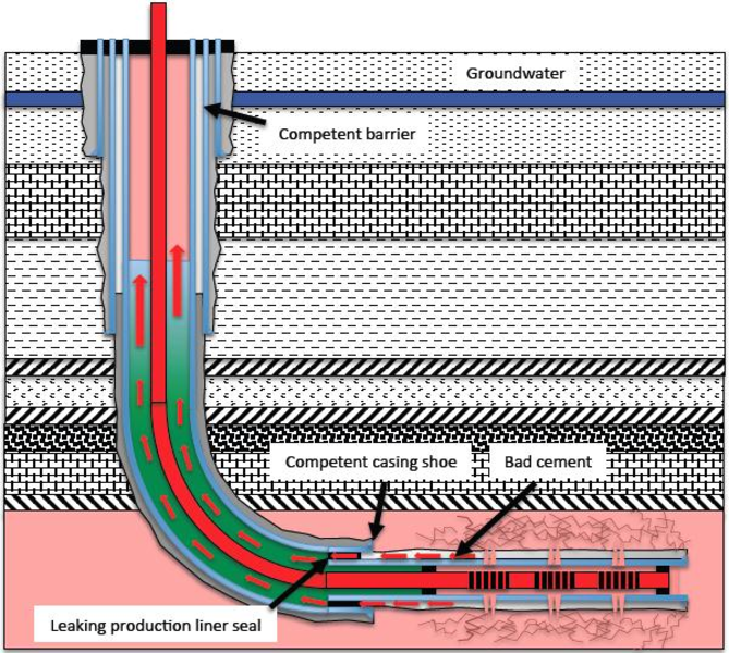 Fig. 5 Scenario of unwanted fluid flow through a badly cemented annulus of the producing section and a leaking production liner hanger seal.
A scenario in which fluids do enter the surrounding rocks is depicted in Figure 6. In this scenario the cement jobs of both the production section and the lower part of the intermediate casing have been badly carried out. Fluids can migrate along the annuli towards permeable rock formations (Fig. 6). The worst case in these scenarios would be fluid migration along the annuli up to groundwater bearing formations. This would suggest
- that cementation is faulty all along the wellbore, from bottom to the top (Fig. 7)
- a lack of other lower pressure and permeable rock formations between the reservoir and the groundwater bearing zone.
If the latter were present, fluids would migrate into these formations and would not migrate further upwards. It has to be stated that loss of well integrity to this extent is hardly conceivable. A range of indicators for cement job quality exists which can be applied during or after individual cementing jobs of the different sections of a well. Careful consideration of these indicators accurately informs operators of the quality of the cementation between rock and steel pipes (see chapter 4). Incidents of integrity loss due to badly cemented well sections are often a result of neglecting due diligence and best practice during well construction.
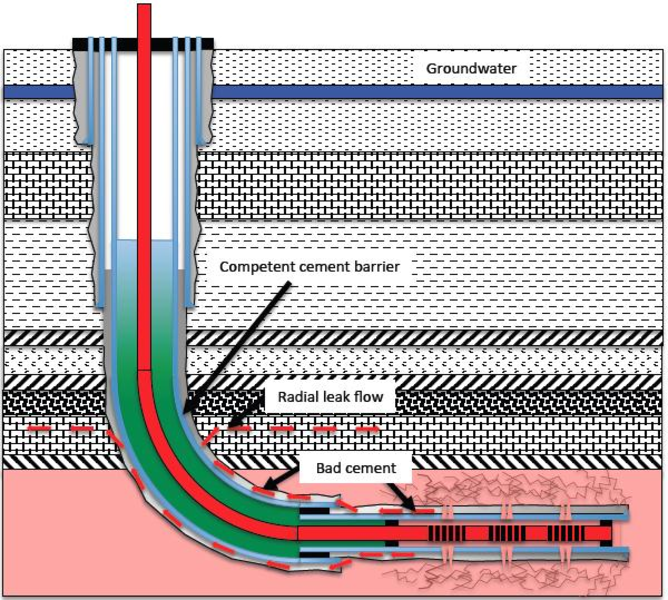 Fig. 6: Leak flow from annulus into rock formation.
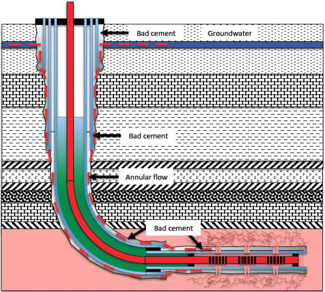 Fig. 7: Failure of all cement barriers.
Casing and Cementing Best Practices
The issue of proper wellbore casing and cementing has been widely discussed by industry and regulators for decades. Major best practices for zonal isolation are listed below, some of which are well known and some of which rely on new technical developments and experience. Many procedures specifically address groundwater protection. They apply to the cementation of all wellbore sections, although special attention must be paid to cementing the surface casing:
- Casing qualities and connections must follow minimum requirements as outlined in API Spec. 5CT.5
- During cementing, the best available mud displacement method to avoid mud channels must be chosen (centralize the casing, condition the borehole, reciprocate and rotate the casing and use spacers in turbulent flow).6
- The use of both top and bottom cementing plugs is highly recommended.7 As the top plug is almost always used, the bottom plug is sometimes left. This is important, however, because it mechanically separates drilling mud from cement slurry inside the casing, minimizing the mixing of fluids during pumping.
- Provide thin and low permeable filter cake from the drilling fluid during the drilling phase and destroy thick filter cakes mechanically by scratchers during running of casing.8 This will reduce the risk of later micro-annuli between cement/formation.
- Reduce cement slurry filtration (< 50ml/30min API fluid loss value) to avoid “bridging” during cement setting with the consequence of uncontrolled “take over” of hydrostatic pressure in the upper parts of the well.9 This is of particular importance when isolating formations with higher pressure or areas with punctuated pressurized biogenic gas pockets in lower parts of the well.
- Reduce slurry chemical shrinkage to a minimum or even consider expanding cement systems to avoid micro annuli between casing/cement and improve the bonding.10
- Volumetric reductions of the slurry during the static transition time after cement pumping (time until the gel strength reaches 500 lb/100ft2) could be filled in with gas, allowing subsequent bubble migration and the formation of micro channels. Slurries with low shrinkage and low filtration values, and high gel strength after pressure balance are recommended to limit bubble migration.11
- The use of right angle setting slurries reduces the amount of time in which gas can migrate within the unset cement.12 Such systems are applied across high-pressure gas zones; they can develop sufficient strength to hinder gas percolation13 (e.g. 500 lb/100ft2) within a short period of time. Thus, gas migration stops within an acceptable distance above the gas entry point.
- The use of lightweight cements avoids cement losses in the case of weak (surface) formation.14 Use lost circulation material if appropriate.
- The use of inflatable annular casing packers (ACP) can significantly enhance a standard cement job by providing specific points of isolation. The positioning of an ACP near a surface casing shoe would ensure a permanent pressure sea.15
- For surface casing applications, cement should always come to the surface, without exclusion. If cement does not appear at the surface during pumping, use parasitic pipe and cement through the annulus.16
- A cement bond log (CBL) should be run to determine the quality of a cement job and to plan a repair squeeze if required. Note that a sufficiently large compressive strength of cement needs to develop during a waiting time (WOC, wait on cement) before performing a CBL test and continuing with drilling operations. Typically WOC times can last up to several days. However, the general reliability of cement bond logs and a calculated cement bond index (BI) has been questioned throughout the literature since decades, e.g. Cement Bond Logging - A New Analysis to Improve Reliability, H. Gai and C. F. Lockyear, BP Research, SPE Advanced Technology Series, Vol. 2, No.1, 1994; Basic Cement Isolation Evaluation, George E. King, P.E., 18 November 2014
- The continuous bounded interval represents the length of continually good quality cement behind a casing. It depends on casing diameter and should follow recommendations17 such as the 33 ft of continuous bounded interval for a 7-in. casing or 45 ft for a 9 5/8-in. casing (recommended by EPA, US Environmental Protection Agency).
- Once a section has been drilled, cased, and cemented, a pressure integrity test of the formation strength immediately below a casing shoe should be performed to ensure that there is an adequate seal at this location to prevent any fluid migration through the casing annulus.18
Risk Potential of Wellbore Integrity Failure vs. Depth
Shale formations occur at a wide range of depths throughout the world. Like in the US where Fayetteville produces from 1,200m and Haynesville from up to 4,500 m, in Europe targets occur from between 900 m and over 4,500 m. Thus, the distance between the shale gas pay zone and groundwater aquifers may vary by some hundreds of meters to several kilometers. Therefore it is necessary to distinguish between different risk potentials for the shallower and deeper cases. This is illustrated by conclusions of a study from the U.S. Department of Energy19 where the risk of groundwater contamination resulting from zonal isolation problems after hydraulic fracturing was classified as low.
- There is often significant vertical separation between the fractured zone and groundwater zones, especially in the majority of deep shale gas plays.
- There are frequently permeable layers of rock between the fractured zone and groundwater that are capable of accepting fluid under pressure. This would lower the available fluid that could reach a groundwater zone.
- There are also frequently layers of rock between the fractured zone and groundwater zone through which vertical flow is restricted; thus serving as a hydraulic barrier to fluid migration.
- The use of advanced computer modeling in fracture design has increased the ability to predict the three dimensional geometry of fracturing; which lowers the likelihood of a fracture job extending into an unintended zone.
Usually shallow shale gas wells (900 - 1500 m) can be drilled using a minimum number of casing sections (e.g. surface, intermediate, horizontal production section). Thus, when considering wellbore integrity, the length of the cemented interval is small compared to deep wellbores and the theoretical risk of a continuous cement failure increases without a sufficient continuous bounded interval. For shallow shale gas wells, a second intermediate casing string would add another barrier to flowing fluids (compare Fig. 4 and Fig. 5).
Conclusions
- Groundwater protection is the most important public concern among environmental issues related to shale gas field development. Therefore, the industry needs to invest further in environmentally acceptable shale gas production technologies, including the best available well construction techniques.
- In several studies it was demonstrated that contamination of groundwater resulting from well integrity failure is very unlikely to happen when existing standards and current best practice are followed1.
- Contamination of groundwater resulting from well integrity failure may arise when best practices are not followed, mainly for cost reasons. However, the high risk of environmental damage and erosion of political and public acceptance is the price to pay in the mid and long term. Any groundwater accidents caused by bad well construction practices would clearly result in a heavy setback of shale gas activities and in the extreme, could lead to the abandonment of whole field development projects.
- We suggest developing standardized guidelines for best practices during cementing jobs. Numerous individual technologies/best practices already exist, but not all are applied in a satisfactory way. Continuously updated and revised guidelines should also include an effective mechanism for monitoring compliance of operators.
1SHIP News: Studies on underground fracturing fluid migration along faults
DiGiulio, D. C. et al., 2011: Investigation of Ground Water Contamination near Pavillion, Wyoming, Report, U.S. EPA
2Osborn, SG, A Vengosh, NR Warner, RB Jackson. 2011. Methane contamination of drinking water accompanying gas-well drilling and hydraulic fracturing. Proceedings of the National Academy of Sciences, U.S.A. 108:8172-8176, dx.doi.org/10.1073/pnas.1100682108
DiGiulio, D. C. et al., 2011: Investigation of Ground Water Contamination near Pavillion, Wyoming, Report, U.S. EPA
3Kell, S. 2011: State Oil and Gas Agency Groundwater Investigations And Their Role in Advancing Regulatory Reforms - A Two-State Review: Ohio and Texas, Report, U.S. Ground Water Protection Council
4Groat, C. G. and Grimshaw, T. W., 2012: Fact-Based Regulation for Environmental Protection in Shale Gas Development, Report, Texas University
6Haut, R. C. and Crook, R. J., 1979: Primary Cementing: The Mud Displacement Process, SPE 8253, Abstract
7Baker Hugher, White Paper: Hydraulic Fracturing: An Environmentally Responsible Technology for Ensuring Our Energy Future, 2012
8Griffith, J. E., Osisanya, S. 1995: Thickness Optimization of Drilling Fluid Filter Cakes for Cement Slurry Filtrate Control and Long-Term Zonal Isolation, SPE 29473. Abstract
9Sutton, F. L. and Sabins, D. L. 1991: Interrelationship Between Critical Cement Properties and Volume Changes During Cement Setting, SPE 20451. Abstract
10Baumgarte, C. et. al. 1999: Case Studies of Expanding Cement To Prevent Microannular Formation, SPE 56535. Abstract
11Prohaska, M. et al. 1995: Modeling Early Time Gas Migration Through Cement Slurries, SPE DC, Summary
12Ashok Santra et al. 2007: Designing Cement Slurries for Preventing Formation Fluid Influx After Placement, SPE 106006, Abstract
13Sabins, F. L. et al., 1982: Transition Time of Cement Slurries Between the Fluid and Set States, SPE 9285, Abstract
14Kulkarni, S. V. and D.S. Hina, D. S. 1999: A Novel Lightweight Cement Slurry And Placement Technique for Covering Weak Shale in Appalachian Basin, SPE 57449, Abstract
15Inflatable Packers, Weatherford, accessed April 2012
16Nelson, E. B. 1990: Well Cementing, Elsevier
17Boyd, D. et al. 2006: Reliability of Cement-Bond-Log Interpretations Compared to Physical Communication Tests Between Formations, SPE 101420, Abstract
18Nobuo Morita et al. 1997: Safety of Casing-Shoe Test and Casing-Shoe Integrity After Testing, SPE 22557-PA, Summary
19U.S. DoE, 2009: State Oil and Natural Gas Regulations Designed to Protect Water Resources, Report.